Taiko’s dry vacuum pump, provided with unique shaped screws, is one of the screw-type pumps that operate most slowly in the world.
Screw type vacuum pump compresses, in one stage, the handled gas with non-contacting operation through from suction to discharge. This achieves the feature that powder and mist accompanying the handled gas are discharge efficiently. For this feature, screw type vacuum pump is widely used as a highly-reliable pump in the industries including semiconductor, liquid crystal, solar battery, pharmaceutical, chemical.
What is Vacuum Pump?
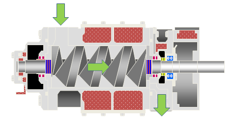
Principle of operation
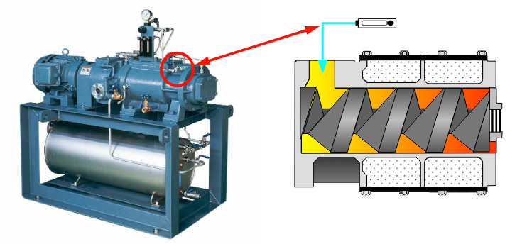
Taiko Kikai’s vacuum pump is provided with a pair of screws in the casing. The screws are assembled together to provide some cavities for capturing the handled gas. The rotation of the screws transfers the captured gas along the shafts.
Queen Bee Screw is adopted in Taiko Kikai’s vacuum pump.
Taiko Kikai’s vacuum pump is dry type vacuum pump, which prevents oil-back-flow to produce a clean vacuum.
Screw rotor
Shape of vacuum pump rotor
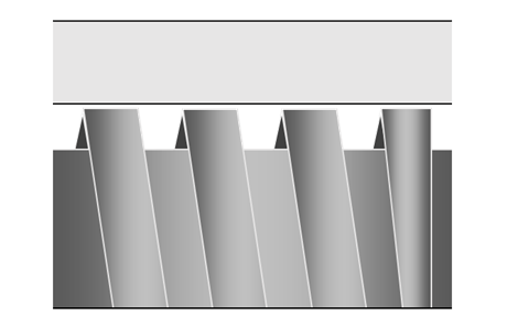
Queen Bee Screw
of Taiko Kikai’s vacuum pump
The rotors closely mesh with each other to minimize the gaps between them. This decreases the internal leakage amount.
Foreign matters can be removed with claw-like shaped vanes.
Less rotation and high efficiency
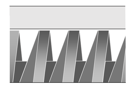
Rectangular-threaded screw
Low capacity tends to let the foreign matter remain inside pump.
Configurations of vacuum pumps
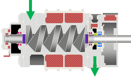
Queen Bee Screw
(Taiko Kikai's vacuum pump)
The flow route is short and has no branches. This minimizes gas agitation and residual particle to discharge the foreign matters, including particle, efficiently.
Less lock-with-particle minimize the failure rate.
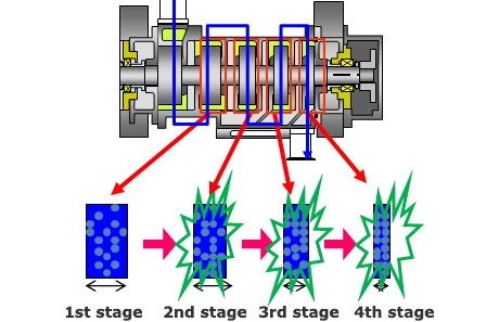
Multi-staged roots claw type impeller
Handled gas is compressed in each cavity in stages. This can lead to lock-with-particle and residual particle in each stage.
Features of Queen Bee Screw
1Less locking and clogging with foreign matters
2Less rotation, smaller noise, smaller vibration
3Queen-Bee-end and tapered-end each has a different shaped screw. This narrows the gap between screws to decrease the internal leak amount
4Handled gas is less likely to liquefy
5Handled gas is less likely to sublime
6Handled gas is less likely to get adhesive
7Extremely low performance-degradation after long term use
8High efficiency ecoVP rotor, which does not require cooling purge, saves energy
Types of vacuum pump screw
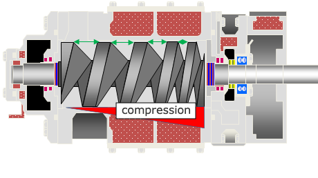
1ecoVP rotor
Gradual continuous compression requires lower power for operation.
Lower discharge temperature, and energy-saving operation.
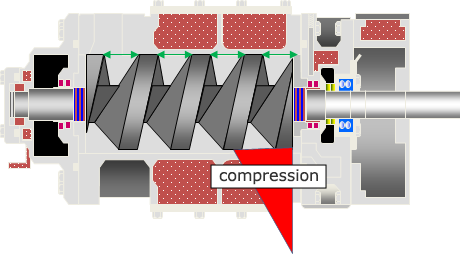
2Equally-pitched screw
Handled gas is compressed at the final stage of the screw, thus the final lead receives a large portion of the work.
Surface finishing
Surface finishing
Surface finishing is performed for decreasing the coefficient of friction of the screw and increasing the anti-corrosion ability of the inside of pump.
1Molybdenum disulfide base
heatproof resin coating
The method for coating the surface of the base material.
2Electroless plating
The method for forming a metal film on the base material by impregnating with plating liquid.
Types of surface finishing
Category of surface finishing
Molybdenum disulfide base heatproof resin coating
Electroless plating
Type of surface finishing
Standard coating
Anti-corrosion organic binder containing coating
Electroless nickel plating
Multi-layered film electroless nickel plating
Fluoro resin fine particle containing electroless nickel plating
Heat resistance
◎
△
◯
◯
△
Corrosion resistance
△
◯
◯
◎
△(Repellency◎)
Coefficient of friction
Low
Low
Somewhat high
Somewhat high
Low
Time of finishing work
Short
Short
Long
Long
Long
Cost
Low
Low
Somewhat high
High
High
Types of purge of vacuum pump
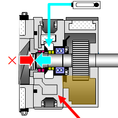
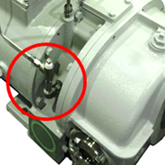
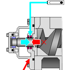
Seal purge
Pressurizing the fluid inside the casing prevents the fluid to go into the side case.
Side case (A)
Drive end
Side case (B)
Driven end
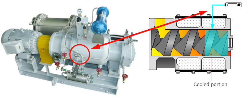
Cooling purge
Cooling purge is introduced from the side of the casing for cooling of the rotor and dilution of corrosive gas.
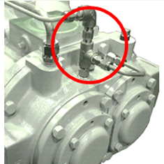
Cleaning purge
Cleaning purge is introduced from the inlet of the pump for cleaning inside the pump.